Why You Should Be Able to Read Structural Drawings
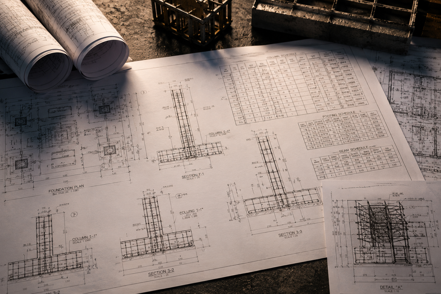
A structural drawing package for a typical G+3 residential building in Oman might contain 40 to 80 sheets: foundation plans, structural floor plans, beam and column schedules, rebar bending schedules, and section and elevation details. Most clients sign off on these drawings having reviewed the architectural sheets in detail and scrolled through the structural package without really understanding what they are looking at. This is understandable — structural drawings are a specialist language. But it is also a risk.
When you cannot read structural drawings, you cannot verify that the design reflects the building you approved, you cannot check whether the contractor is building to the drawings, and you cannot have an informed conversation with your structural engineer when questions arise on site. This guide does not aim to make you a structural engineer. It aims to give you enough literacy to protect your interests as a client, developer, or site supervisor in Oman's construction market.
The Main Types of Structural Drawings
A complete structural drawing set is organised into a hierarchy of documents, each serving a different purpose. Understanding what each sheet type is trying to communicate is the first step to reading the package effectively.
- Foundation Plans show the layout and dimensions of all below-ground structural elements — pile positions, pile cap shapes and sizes, grade beams, and ground-floor slab thickness and reinforcement.
- Structural Floor Plans (or framing plans) show the column grid, beam locations, slab thicknesses, and any penetrations or openings at each floor level.
- Reinforcement Drawings detail the size, spacing, and placement of steel reinforcement bars (rebar) within each concrete element.
- Rebar Bending Schedules are tables listing every bar in the structure — its mark number, diameter, shape code, and cut length — used for bar fabrication and delivery.
- Section and Elevation Details are cut-through views showing how structural elements connect, bearing conditions, step changes in slab level, and connection geometry.
- General Notes and Specifications list material grades (concrete strength, rebar grade), design standards (ACI 318, BS 8110, or the Oman NBC), cover requirements, and construction tolerances.
Foundation Plans: What to Look For
The foundation plan is typically the first structural sheet a contractor works from, and it carries the most long-term consequence of any drawing in the package. Errors in foundations cannot be corrected without extraordinary cost. When reviewing a foundation plan, focus on four things.
First, check that the column grid on the foundation plan matches the column grid on the architectural drawings. Column positions that shift between the architectural and structural packages are a common coordination failure that causes expensive field problems. Second, look at the pile cap or isolated footing dimensions and verify they are consistent with the geotechnical investigation report recommendations for soil bearing capacity. Third, confirm that grade beams — the reinforced beams connecting pile caps or footings — are shown on all sides of the structure, not just on the perimeter. Fourth, check that the concrete slab-on-grade thickness and reinforcement specification are shown, not just assumed.
Structural Floor Plans and Framing Layouts
Structural floor plans show the skeleton of each floor level. The column grid — typically labelled with letters on one axis and numbers on the other (e.g., Grid A, Grid 1) — is the organisational reference for the entire structure. Every column, beam, and slab is located relative to this grid. When reviewing a structural floor plan, verify that the column grid spacing matches the spans shown on the architectural plan. Long spans without intermediate columns or beams usually indicate a deep or heavily reinforced beam — check that the structural depth is coordinated with the ceiling height in the architectural drawings, otherwise you will discover a conflict when the formwork is set.
Slab thicknesses are typically noted in a slab schedule or directly on the plan, often as 'S1 = 180mm' or similar notation. In Oman's climate, post-tensioned flat slabs are common on commercial projects above three storeys — if your project uses post-tensioning, the structural drawings should include a separate set of tendon layout plans and a specialist contractor's shop drawing review process.
Pile layout, pile cap dimensions, grade beam locations, and slab-on-grade specifications for all below-ground structure.
Column and beam grid layout, slab depths, and openings at each floor level — the skeleton of the building above ground.
Bar mark, diameter, bending shape codes, lap lengths, and cut lengths for every reinforcement bar in the structure.
Cut-through views showing connection details, bearing conditions, step changes, and construction joint locations.
Reinforcement Drawings and Rebar Schedules
Reinforcement drawings show where, how much, and in what configuration steel rebar is placed within each concrete element. A beam reinforcement drawing will show the main longitudinal bars at the top and bottom of the beam, the shear links or stirrups that hold them in position and resist diagonal cracking, and the development lengths (how far bars extend past their required point of termination). A column reinforcement drawing shows the main vertical bars and the ties or hoops that confine the concrete core under load.
The rebar schedule is the fabrication document — it lists every unique bar shape in the structure with a mark number, bar diameter (e.g., T16 for 16mm high-yield bar), bending shape code (referencing standard BS 8666 or ACI 318 schedules), and the total number of each bar required. When reviewing a rebar schedule as a client, the most useful check is confirming that the bar diameters specified match the bar diameters noted on the reinforcement drawings. Discrepancies between the schedule and the plan are a common quality-control failure.
Section Drawings and Elevation Details
Section drawings are vertical slices through the building — imagine cutting the structure in half and looking at the cut face. They show the relationship between floor levels, the depth of beams relative to the slab soffit, the height of columns between floors, and how structural elements connect at joints. A key detail on any section drawing is the bearing condition — how a beam or slab lands on a supporting element — and whether there is adequate bearing length to transfer load safely.
Construction joint locations are also shown on section drawings. A construction joint is a planned stop-start point in the concrete pour sequence. In Oman's climate, where concrete placement often occurs in high-temperature conditions, construction joint planning is critical for avoiding thermal cracking. Check that construction joints are shown at logical locations (mid-span, not at maximum moment zones) and that the structural drawings include a note on how the joint surface should be prepared before the next pour.
Key Symbols and Abbreviations Explained
Structural drawings use a standardised set of symbols and abbreviations that appear across all drawing types. Becoming familiar with the most common ones will unlock the majority of what you need to read. The column grid lines are shown as circles with letters or numbers on the drawing border — all elements are located by their intersection coordinates (e.g., "Column at B3"). Bar diameters are noted with a T prefix for high-yield deformed bars (T12, T16, T20, T25, T32) and an R prefix for mild steel plain bars (R8, R10). Spacing of bars is shown as a pitch notation — T12@200 means 12mm high-yield bars at 200mm centres.
EW means "each way" (bars running in both horizontal directions), EF means "each face," and BRC refers to a welded wire mesh fabric. Cover refers to the clear distance between the outside face of the concrete and the nearest rebar surface — critical for durability in Oman's coastal and high-humidity environments. The general notes sheet will specify the minimum cover for each exposure condition.
Red Flags to Watch For
Certain patterns in a structural drawing package should prompt you to ask questions before construction proceeds. Watch for column grids that do not align between architectural and structural drawings — this indicates a coordination failure. Be wary of general notes that reference design standards but do not specify concrete grades or rebar grades — "as per engineer's specification" without a specification document attached is not sufficient for contractor pricing or quality control. Check that drawing revision clouds are dated and that the revision history in the title block is complete — working from superseded drawings is one of the most common causes of costly rework on site.
If the structural package does not include a design basis statement — a document setting out the loads, design codes, geotechnical parameters, and structural system used — ask for one before signing off. At First Step Engineering, every structural package we deliver includes a full design basis statement, revision control, and a client briefing session so that you understand exactly what you are approving. Contact us if you have an existing package you would like us to peer-review.